Voltage Droop Control with Deadband Dialog
The ability to use a Voltage Droop Control with Deadband was added in Simulator Version 21
Some generator voltage controls are configured such that the control signals sent to the generator are related to the measurements made at a remote bus instead of the terminal buses. An example of this is renewable generation plants such as a large solar farm or wind generation farm. In a common configuration the power system model for this situation will be as follows. The theory of this setup is described in the help topic Power Flow: Voltage Droop Control with Deadband.
To configure this type of control for a group of generators you must first create a VoltageDroopControl object and then second assign generators to this VoltageDroopControl. The VoltageDroopControl object defines the QV characteristic curve that will be followed by the group and then assigning generators to that VoltageDroopControl defines the group of generators that will participate in this control. The regulated bus of the generators defines where in the system the QV characteristic control is assigned.
Do define VoltageDroopControl objects, go to the Model Explorer and under the Network Folder choose the Voltage Droop Controls to bring up the Voltage Droop Control Case Information Display. Then right-click on this case information display and choose Insert to add a new VoltageDroopControl. The dialog that appears is as follows.

The ability to specify a regulated bus with a VoltageDroopControl was added in the Version 21 build on Febraury 5, 2021.
A VoltageDroopControl object may have a Regulated Bus specified with it. If the Regulated Bus is specified, then all generators assigned to that VoltageDroopControl will automatically use this regulated bus. If the value is unspecified, Simulator will create a unique Voltage Droop Control equation for each set of generators within the voltage droop control which share a regulated bus (or buses connected by low impedance branches). To specify the Regulated Bus, click the Choose button or double-click on any of the edit boxes showing information about the regulated bus.
This dialog has three tabs
- Generators: This tab contains a case information display showing the generators in the case that have been assigned to belong to the VoltageDroopControl on this dialog
- All Generators in Model: This tab contains a case information display showing all the generators in the entire model. You can go to this tab to assign generators to the Voltage Droop Control
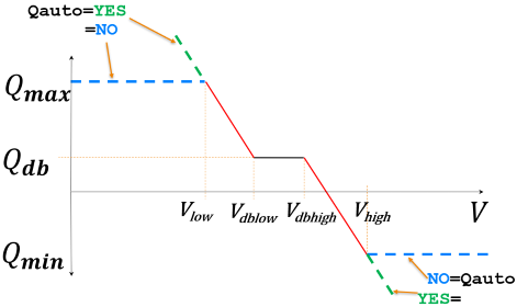
- QV Characteristic: This tab is where you define the QV characteristic curve by specifying the various per unit voltage and reactive Mvar flow thresholds along the QV characteristic curve. Enter Vlow, Vdblow, VdbHigh, VHIgh, Qmax, Qdb, and Qmin to define the curve. It may also be convenient to specify that the Qdb, Qmax, and Qmin values be automatically calculated based on the summation of generator MvarMax and MvarMin, and Qdb is assumed to be 0.0. (If both Qmax and Qmin are the same sign, then Qdb is assumed to be either Qmax or Qmin depending on which value is closer to 0.0). When automatically determine the reactive thresholds for this curve, there is no need to actually enforce those limits in the QV Characteristic curve. Instead we can just rely on the individual generators to enforce their Mvar limits. As a result the QV characteristic curve would change as depicted in the following image. When Qauto is chosen then the red line extrapolates out as shown in the green dashed line